RC Market Home UltraPAC UltraPAC II Manuals Service Menu Order FlySafe series FlySafe 3
To access those menus you need an UltraPAC II (256K or 512K).
UltraPAC-64K does not have access to this feature.
Please note: This page may take a while to load due to the large amount of photographs.
Service Menu Main Screen
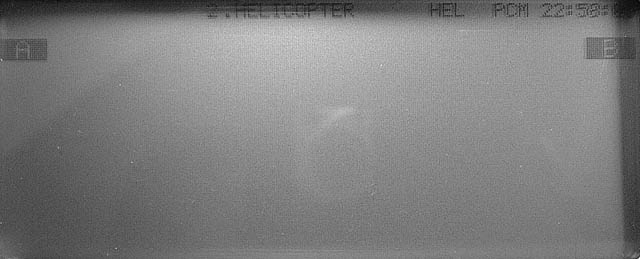
2.HELICOPTER = Stick Mode 2, helicopter version (T9ZHP)
[A] takes you to "ID AND TIME" and "SWITCH TYPE" screens
[B] takes you to every other screen
ID AND TIME
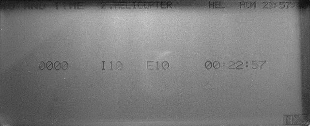
0000 = ID number (password)
I10 = internal firmware version 1.0
E10 = external ROM contains firmware version 1.0
00:22:57 = Total usage time (hours x100 : hours : minutes)
SWITCH TYPE
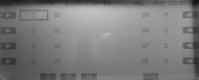
This screen allows customization of the switch configuration. Obviously physical replacement of the switch is also required. All types of switches have the same number of contacts and identical footprint which makes direct replacement possible.
Select the switch you wish to modify, then choose between [2], [3] or [M]
2 = 2-position switch
3 = 3-position switch
M = momentary switch
SA - SH = Switch A - Switch H
SWITCH REV
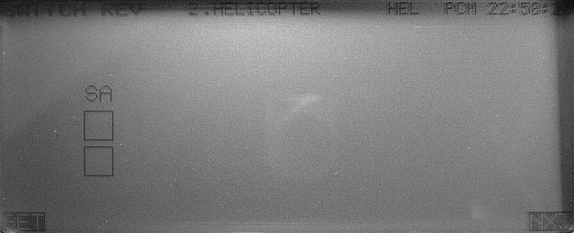
Calibration process for the toggle switches:
Press [SET], toggle switch A, press [SET]
(Do not calibrate the middle position of switch A - if such position exists on your radio)
Confirmation of successful calibration: Both boxes should become black.
NEUTRAL REV
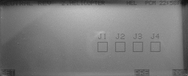
Neutral calibration process for the joysticks:
Set all sticks to neutral (centre) including throttle, Press [SET]
Confirmation of successful calibration: All four boxes should become black.
WIDE REV
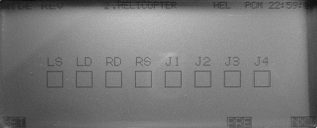
Move both sticks fully right and fully down, set knobs fully clockwise and sliders fully down. Press [SET]
Confirmation of successful calibration: All eight boxes should become black.
Note: These controls can be calibrated individually. Any control that we do not wish to calibrate must remain at the centre of its range.
NARROW REV
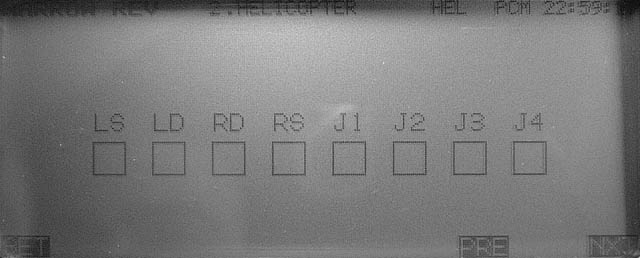
Move both sticks fully left and fully up, set knobs fully anticlockwise and sliders fully up. Press [SET]
Confirmation of successful calibration: All eight boxes should become black.
Note: These controls can be calibrated individually. Any control that we do not wish to calibrate must remain at the centre of its range.
VOLTAGES (calibration)
Voltmeter calibration procedure:
Two calibrated power supplies are required.
Set the battery voltage to 8.5+/-0.2V and the receiver voltage input (DIN connector, Pin.6) to 5+/-0.2V. Press [SET]
Confirmation of successful calibration: None at this stage. However, voltage check is available at later screens.
SWITCHES
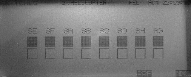
Toggle switch check. Move switches to all position.
All boxes should become black.
TRIM BUTTONS
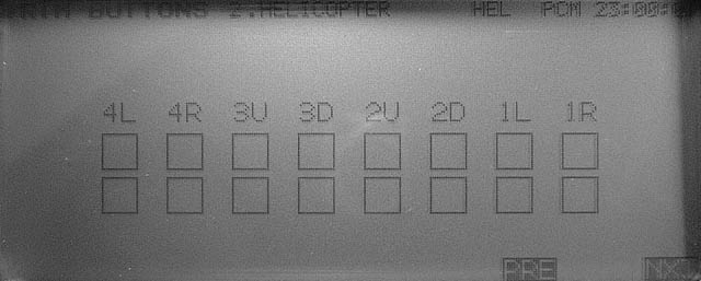
Operate the trims and confirm that the corresponding box is turned black.
Top line corresponds to normal trim.
Bottom line corresponds to fast trim (harder press of the switch).
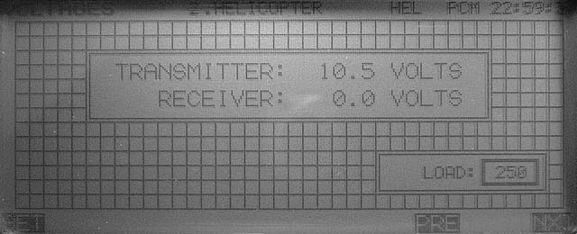
VOLTAGES (check)
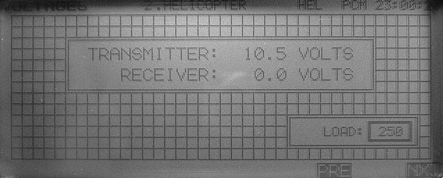
Two calibrated power supplies are required.
Set the battery voltage to 8.5V and the receiver voltage input (DIN connector, Pin.6) to 5V
Confirm that displayed voltages are within ń0.2V of power supply voltage.
TACHOMETER
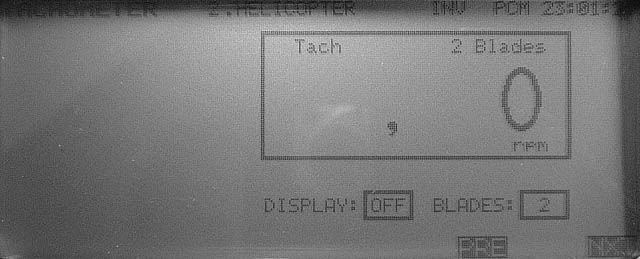
Check tachometer operation.
Procedure: Position tachometer sensor near a fluorescent light tube or TV screen (not computer monitor).
Reading should be:
3000 +/- 20rpm fluorescent light at 50Hz (Europe)
3600 +/- 20rpm fluorescent light at 60Hz (USA)
1500rpm +/- 10rpm PAL TV (Europe)
1800rpm +/- 10rpm NTSC TV (USA)
IO PORT
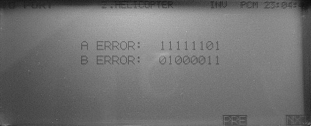
This is a hardware test that requires some technical knowledge. Here is what these numbers represent:
LSB at right.
bit7 = PLL connector, RFCONT pin
bit6 = PLL connector, CLOCK pin
bit5 = PLL connector, DATA pin
bit4 = PLL connector, LE pin
bit3 = CAMPac connector, Pin.2
bit2 = CAMPac connector, Pin.3
bit1 = DIN connector, Pin.3
bit0 = RF module connector, METER pin
All pins are configured as inputs for this test although some function as outputs during normal operation. A ERROR indicates the state of these pins when this screen is entered. If the state of these pins change A ERROR is not updated. However B ERROR shows `1' for any of these pins that transitioned from high to low.
LCD DISPLAY
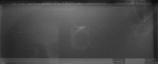
The big dark section blinks on/off. Confirm there are no "dead pixels" (white dots) in this area.
EDIT KEYS
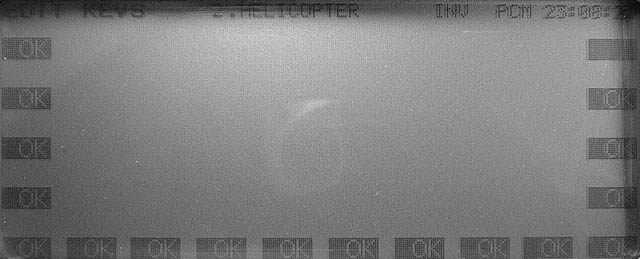
Press all keys from A to R. The corresponding box displays [OK].
Once all keys are pressed you will be prompted to exit the service menu or return to the previous screen.
You may not redistribute any text or pictures without prior written permission.